|
The test rig was designed in order to target and repetitious adjust a multiplicity of
possible influencing factors for wear. Potential influencing factors might be: coercive rotation, coercive oscillation and
still standing of the tappet; oil conditioning (temperature and lubrication condition in contact point); separation of cam
base circle and cam tip; different eccentricity between cam lobe and tappet; static and dynamic application of different
contact load. For a reduction of effects from other contact points, the test rig consists only one cam lobe-tappet-contact
as well as the two corresponding cam lobe bearings. |
|||||||||||||||||||
| Shematic diagram: | |||||||||||||||||||
|
|||||||||||||||||||
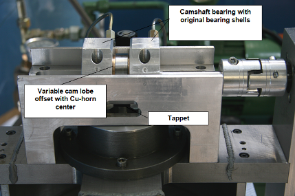
| Lateral view: | |||||||||||||||||||
 |
|||||||||||||||||||
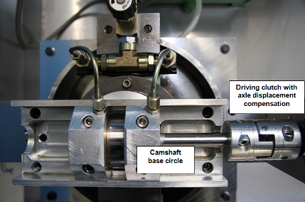
| Top view: | |||||||||||||||||||
 |
|||||||||||||||||||
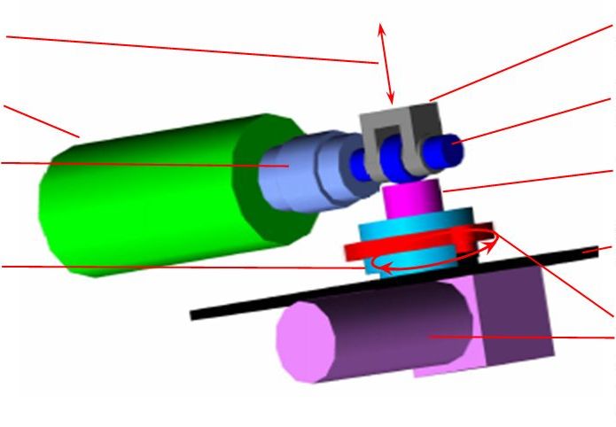
cam lobe-tappet-contact